
MAP PROJECTION//its TYPE
Map projection is the method of transferring the graticule of latitude and longitude on a plane surface. It can also be defined as the transformation of spherical network of parallels and meridians on a plane surface.
The method by which we transform the earth’s spheroid (real world) to a flat surface (abstraction), either on paper or digitally
the spatial relationship between locations on earth and their relative locations on a flat map
Classifications of Map Projections
On the basis of Intrinsic Properties
Conformal – local shapes are preserved e.g. Mercator’s Projection
Equal-Area – areas are preserved. e.g. Bonne’s Projection, Cylindrical Equal Area Projection
Equidistant – distance from a single location to all other locations are preserved e.g. Simple conical projection with one standard parallel.
Azimuthal – directions from a single location to all other locations are preserved. e.g. Zenithal Stereographic Projection
Another Classification System
On the basis of Extrinsic PropertyPlane/Surface of Projection
Planar-e.g. Zenithal Stereographic Projection= Earth intersects the plane on a small circle. All points on circle have no scale distortion.
Cylindrical- e.g. Simple Conical Projection with One standard Parallel, Bonne’s Projection= Earth intersects the cylinder on two small circles. All points along both circles have no scale distortion.
Conic - e.g. Mercator’s Projection, Cylindrical Equal Area Projection=Earth intersects the cone at two circles. All points along both circles have no scale distortion.
Another Classification System
On the basis of Extrinsic Property Method of Projection
Perspective Projection: Here graticules are drawn from a transparent generating globe made of glass with the help of a light source. Rays emerging from the sources cast shadows of parallels and meridians on the projection plane.
Semi-Perspective Projection: In this case, one set of intersecting lines are geometrically projected and the other set drawn purely to suit a desired property.
Non-Perspective Projection : In this case, projection is done in accordance to a consistent principle to satisfy certain objectives.
Conventional Projection : In this case projection is constructed following a set of conventions purely based on mathematical operations postulated by a cartographer.
Some Projection Parameters
Standard parallels and meridians – the place where the projected surface intersects the earth – there is no scale distortion. Along the standard parallels, tangential scales essentially 1:1.
Central meridian –The meridian which lies exactly at the median or middle position. It has constructional importance, usually drawn as a straight line and is commonly divided true to scale for spacing the parallels along it. The net of graticules on one side of the central meridian is infact the replica of the other side.
Graticule : It refers to the net of mutually intersecting parallels and meridians drawn to a certain scale and based on certain principles.
Spherical Coordinates- The position of a point on the earth’s surface is usually determined with respect to an imaginary reference framework constituted by a fixed pair of mutually intersecting perpendicular lines - equator and prime meridian. The ordinate values are the latitudes while the abcissa values are longitudes.
Generating Globe: It refers to the globe from which projections are generated or developed. Normally this is a small skeleton globe made of glass or wire. The parallels and meridians are shown by black lines or wires (wire globe) placed at their true angular distances apart. Naturally the generating globe is a geometrically accurate earth reduced in size.
Projection Plane: It is a two-dimensional geometric plane upon which the parallels and meridians are usually projected. In case of a perspective planar projection the projection plane touches the generating globe at a single point.
Polar Zenithal Stereographic Projection

Principle : The plane of projection is tangent at either of the poles. The parallels of latitude are projected as concentric circles- closer towards the centre and farther apart towards the edges. The meridians are radiating straight lines at true angular distances apart.
Properties :
The property of correct azimuths or true bearings from the centre of the map or projection is retained
. Those great circles which pass through the source of light and the point of tangency of the plane of projection are projected as straight lines.
The exaggeration of scales-both tangential and radial away from the centre is nevertheless appreciable.
Limitations: The antipode of the point of tangency of the plane of projection with the generating globe cannot be represented .

Bonne’s Projection
Principle : In this projection, each parallel is divided truly- a modification from the previous projection introduced to make the scale along the parallels correct and therefore to make the projection an equal-area one.
Properties : The scale is correct along each parallel and as the parallels are arcs of concentric circles and the central meridian is truly divided the scale is correct in directions perpendicular to the parallels at all points .
The scale along the central meridian is true; along other meridians there is exaggeration which increases away from the central meridian.
The projection is an equal-area one.
Limitations : Its defects are accentuated if the range of longitude s increased.
Conical Projection with one Standard Parallel
A conical projection is one, which is drawn by projecting the image of the graticule of a globe on a developable cone, which touches the globe along a parallel of latitude called the standard parallel. As the cone touches the globe located along AB, the position of this parallel on the globe coinciding with that on the cone is taken as the standard parallel. The length of other parallels on either side of this parallel are distorted.

Properties
1. All the parallels are arcs of concentric circle and are equally spaced.
2. All meridians are straight lines merging at the pole. The meridians intersect the parallels at right angles.
3. The scale along all meridians is true, i.e. distances along the meridians are accurate.
4. An arc of a circle represents the pole.
5. The scale is true along the standard parallel but exaggerated away from the standard parallel.
6. Meridians become closer to each other towards the pole.
7. This projection is neither equal area nor orthomorphic.
Limitations
1. It is not suitable for a world map due to extreme distortions in the hemisphere opposite the one in which the standard parallel is selected.
2. Even within the hemisphere, it is not suitable for representing larger areas as the distortion along the pole and near the equator is larger.
Uses
1. This projection is commonly used for showing areas of mid-latitudes with limited latitudinal and larger longitudinal extent.
2. A long narrow strip of land running parallel to the standard parallel and having east-west stretch is correctly shown on this projection.
3. Direction along standard parallel is used to show railways, roads, narrow river valleys and international boundaries.
4. This projection is suitable for showing the Canadian Pacific Railways, Trans-Siberian Railways, international boundaries between USA and Canada and the Narmada Valley.
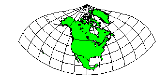
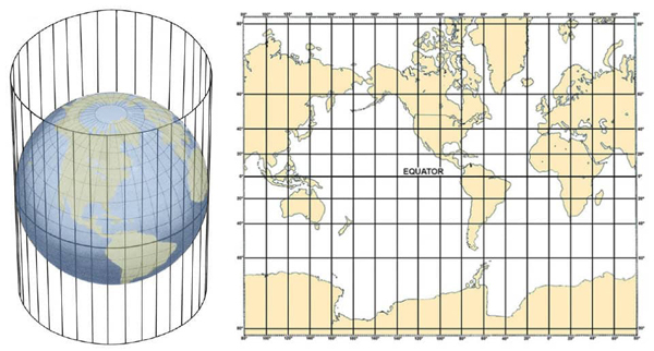
Cylindrical Equal Area Projection
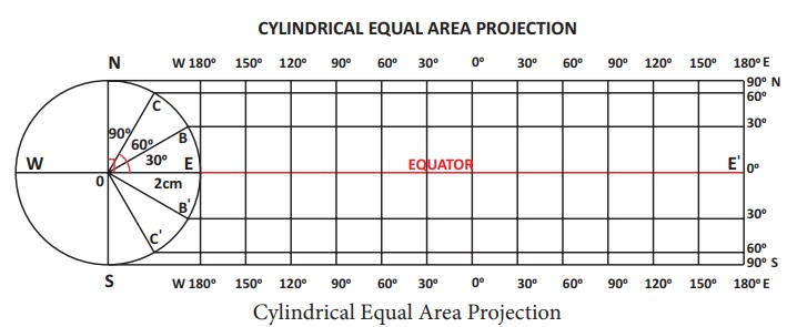
The cylindrical equal area projection, also known as the Lambert’s projection, has been derived by projecting the surface of the globe with parallel rays on a cylinder touching it at the equator. Both the parallels and meridians are projected as straight lines intersecting one another at right angles. The pole is shown with a parallel equal to the equator; hence, the shape of the area gets highly distorted at the higher latitude.
Properties
1. All parallels and meridians are straight lines intersecting each other at right angle.
2. Polar parallel is also equal to the equator.
3. Scale is true only along the equator.
Limitations
1. Distortion increases as we move towards the pole.
2. The projection is non-orthomorphic.
3. Equality of area is maintained at the cost of distortion in shape.
Uses
1. The projection is most suitable for the area lying between 45º N and S latitudes.
2. It is suitable to show the distribution of tropical crops like rice, tea, coffee, rubber and sugarcane.
Mercator’s Projection
A Dutch cartographer Mercator Gerardus Karmer developed this projection in 1569. The projection is based on mathematical formulae. So, it is an orthomorphic projection in which the correct shape is maintained. The distance between parallels increases towards the pole. Like cylindrical projection, the parallels and meridians intersect each other at right angle. It has the characteristics of showing correct directions. A straight line joining any two points on this projection gives a constant bearing, which is called a Laxodrome or Rhumb line.
Properties
1. All parallels and meridians are straight lines and they intersect each other at right angles.
2. All parallels have the same length which is equal to the length of equator.
3. All meridians have the same length and equal spacing. But they are longer than the corresponding meridian on the globe.
4. Spacing between parallels increases towards the pole.
5. Scale along the equator is correct as it is equal to the length of the equator on the globe; but other parallels are longer than the corresponding parallel on the globe; hence the scale is not correct along them. For example, the 30º parallel is 1.154 times longer than the corresponding parallel on the globe.
6. Shape of the area is maintained, but at the higher latitudes distortion takes place.
7. The shape of small countries near the equator is truly preserved while it increases towards poles.
8. It is an azimuthal projection.
9. This is an orthomorphic projection as scale along the meridian is equal to the scale along the parallel.
Limitations
1. There is greater exaggeration of scale along the parallels and meridians in high latitudes. As a result, size of the countries near the pole is highly exaggerated. For example, the size of Greenland equals to the size of USA, whereas it is 1/10th of USA.
2. Poles in this projection cannot be shown as 90º parallel and meridian touching them are infinite.
Uses
1. More suitable for a world map and widely used in preparing atlas maps.
2. Very useful for navigation purposes showing sea routes and air routes.
3. Drainage pattern, ocean currents, temperature, winds and their directions, distribution of worldwide rainfall and other weather elements are appropriately shown on this map.


.png)


.png)


0 Comments